Armature Reaction:
The effect of magnetic field set up by
armature current on the distribution of flux under main poles of a generator.
The armature magnetic field has two effects:
It demagnetises or weakens the main flux and
It cross-magnetises or distorts it. Fig 1 shows the flux distribution of a bipolargenerator when there is no current in the armature conductors. The brushes are touching the armature conductors directly, although in practice, they touch commutator segments, it is seen that: (a) the flux is distributed symmetrically with respect to the polar axis, which is the line joining the centres of NS poles. (b) The magnetic neutral axis (M.N.A.) coincides with the geometrical neutral axis (G.N.A.). Magnetic neutral axis may be defined as the axis along which no emf is produced in the armature conductors because they move parallel to the lines of flux. Or M.N.A. is the axis which is perpendicular to the flux passing through the armature.

Brushes are always placed along M.N.A. Hence, M.N.A. is also called ‘axis of commutation’ because reversal of current in armature conductors takes place across this axis. Vector OF m which represents, both magnitude and direction, the mmf of producing the main flux. Fig 2 shows the field (or flux) set up by the armature conductors alone when carrying current, the field coils being unexcited. The current direction is downwards in conductors under N-pole and upwards in those under S-pole.
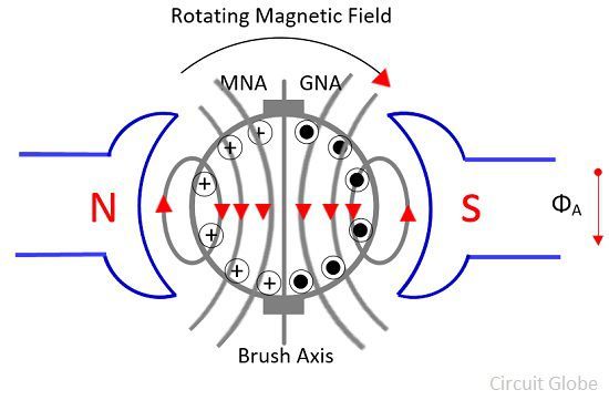
The armature mmf (depending on the strength of the armature current) is shown separately both in magnitude and direction by the vector OFA. Under actual load conditions, the two mmf exist simultaneously in the generator as shown in Fig. 3. It is seen that the flux through the armature is no longer uniform and symmetrical about the pole axis, rather it has been distorted. The flux is seen to be crowded at the trailing pole tips but weakened or thinned out at the leading pole tips (the pole tip which is first met during rotation by armature conductors is known as the leading pole tip and the other as trailing pole tip). The strengthening and weakening of flux is separately shown for a four-pole machine.

In Fig.3 is shown the resultant mmf OF
(The new position of M.N.A.) which is found by vectorially combining OFm and
OFA. And the new position of M.N.A which is always perpendicular to the
resultant mmf vector OF, is also shown in the figure. With the shift of M.N.A.,
say through an angle θ brushes are also shifted so as to lie along the new position of M.N.A. Due to this brush shift ,
the armature conductors and hence armature current is redistributed. All
conductors to the left of new position of M.N.A. but between the two brushes,
carry current downwards and those to the right carry current upwards. The
armature mmf is found to lie in the direction of the new position of M.N.A. (or
brush axis). The armature mmf is now represented by the vector OFA. OFA can now
be resolved into two rectangular components, OFd parallel to polar axis and OFC
perpendicular to this axis. We find that:
Component OFC is at right
angles to the vector OFm representing the main mmf It produces distortion in
the main field and is hence called the cross-magnetising or distorting
component of the armature reaction.
The component OFd is in direct
opposition of OFm which represents the main mmfIt exerts a demagnetising
influence on the main pole flux. Hence, it is called the demagnetising or
weakening component of the armature reaction.
It should be noted that both distorting
and demagnetising effects will increase with increase in the armature current.
Related Articles
Lesson meta keywords and meta description:
Write a public review