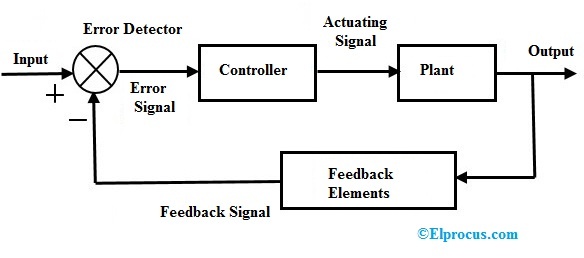
The output C(s) is fed
back to the summing point, where it is compared with reference input R(s). The
closed loop nature is indicated in fig1.3. Any linear system may be
represented by a block diagram
consisting of blocks, summing points and branch points. A branch is the point
from which the output signal from a block diagram goes concurrently to other
blocks or summing points.
When the output is fed back to the summing point for comparison with the input, it is necessary to convert the form of output signal to that of he input signal. This conversion is followed by the feed backelement whose transfer function is H(s) . Another important role of the feed back element is to modify the output before it is compared with the input.
C(s)[1
+ G(s)H(s)] = G(s)R(s)
open loop transfer function = B(s)/E(s) = G(s)H(s)
Feed forward transfer function = C(s)/E(s) = G(s)
If
the feed back transfer function is unity, then the open loop and feed forward
transfer function are the same. For the system shown the output C(s)
and input R(s) are related as follows.
C(s) = G(s) E(s)
E(s) = R(s) - B(s)
Eliminating E(s) from these equations
C(s) + G(s)[H(s)C(s)] = G(s)R(s)
C(s)[1 + G(s)H(s)] = G(s)R(s)
C(s)/R(s) is called the closed loop transfer function
The
output of the closed loop system clearly depends on both the closed loop
transfer function and the nature of the input. If the feed back signal is
positive.
Related Articles
Lesson meta keywords and meta description:
Write a public review