The
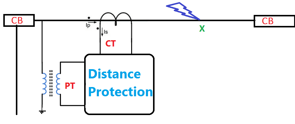
basic principle involved in the above figure explains the division of the
voltage at the relay by the measured current. The absolute impedance is
compared with the reach point impedance If the measured impedance is less than
the reach point impedance, it is assumed that a fault exists on the line
between the relay and the reach point.
The
reach point of the relay is the point along the line impedance locus that is
intersected by the boundary characteristics of the relay. Distance relay is the
broader name of the different types of impedance relay.
The relay is connected at position , R and
receives a secondary current iF, equivalent to a primary fault current , IF.
The secondary voltage , VF, is equivalent to the product of the fault current
“IF” and impedance of the line up to the point of fault, ZF. The operating
torque o f this relay is proportional to the fault current “IF”, and its
restraining torque is proportional to the voltage “VF”.
Taking
into account the number of turns of each coil, there will be a definite ratio
of V/I at which the torque will be equal. This is the reach point setting of
the relay. The relay will operate whe n the operating torque is greater than
the restraining torque .Thus any increases in current coil ampere - turn s ,
without a corresponding increase in the voltage coil ampere - turns , will
unbalance the relay. This means the V/ I ratio has fallen below the reach
point. Alternatively if the restrain torque is greater than the operating
torque , the relay will restrain and its contacts will remain open[8] . In this
case the V/I ratio is above the reach point. The reach of a relay is the
distance from the relaying point to the point of fault. Voltage on the primary
voltage transformer , VT , is :
V
= EZF/ZS +Z F
The
Relay compare the secondary values of V and I as to measure their ratio which
is called measured impedance Zm
ZM
= ZF * C T Ratio/ P T
Ratio
Related Articles
Lesson meta keywords and meta description:
Write a public review